
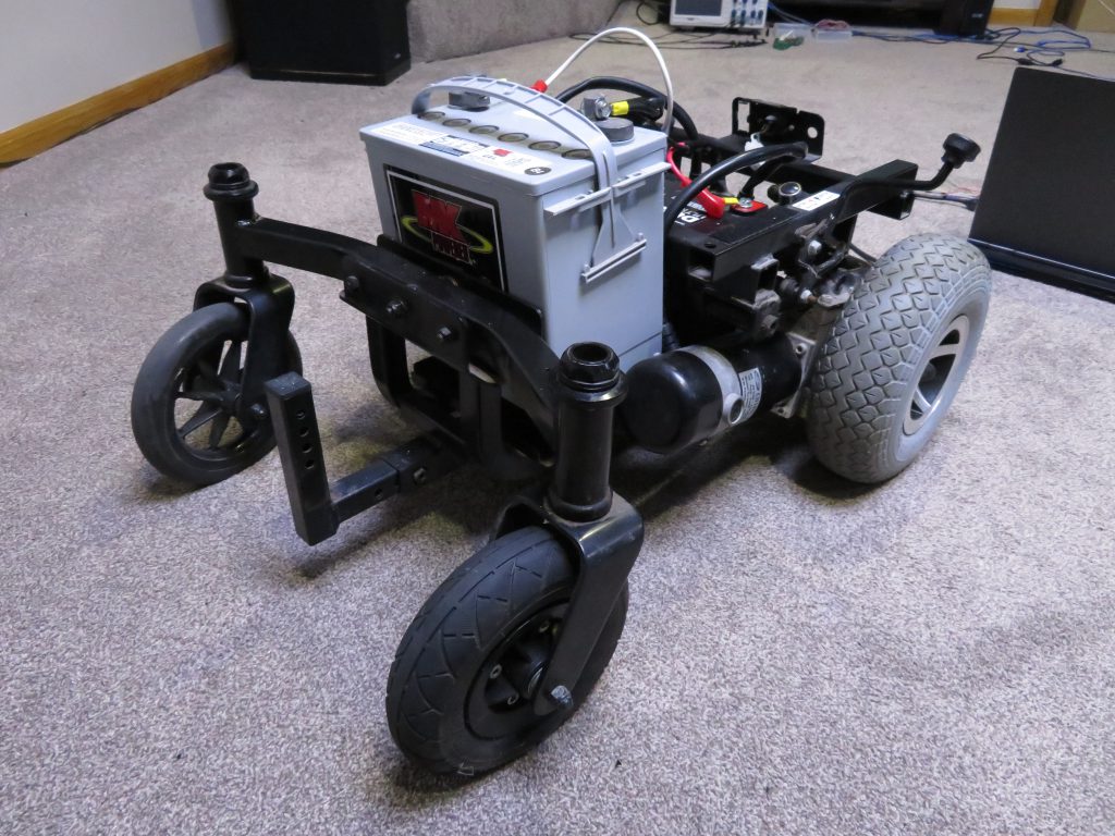
The Backstory
A few months ago I was presented with an opportunity to buy a set of severely damaged mobility scooters. One of the tri-wheel type, and one of the zero turn type. The one we’re focusing on today is the zero-turn type. Upon initial examination it was clear that the previous owner had made some modifications to the system, and did not quite know what they were doing, but that is besides the point. After cleaning it up and replacing the batteries with two functioning ones, I was able to power up the mobility scooter and get it to drive around using the Dynamic Controls joystick.
Now I had a half destroyed mobility scooter, with two mismatching front wheels and the seat weathered so badly that it was pointless to try to restore this thing. I decided to do what any hacker would do; give damaged electronics new life in the form of something else! So this is where I came up with the brilliant idea of creating an autonomous self-navigating robot just for the heck of it. This blog post describes the first part of the process of building such a robot; getting it to move. Obviously I was at a point where I had existing hardware and didn’t want to spend much money on it.
The first thing I did was pop apart the original joystick controller. This alone didn’t tell me much. I figured worst case I could use an Arduino to manually control the forward/reverse/left/right inputs from the joystick in order to interface with the power controller. I was wrong. The joystick was an inductive joystick, and the microcontroller read the raw values directly, so tricking it was going to be more complicated than just trying to interface with the power controller directly.
We now arrive at the entire point of this post; controlling the power controller directly, with no tether to the original joystick. I started by seeing if anyone else had done this, at first glance, I found little information, some people had attempted this but given up. This was perfect, because I enjoy a challenge. Eventually I found a post over at wheelchairdriver.com from a user asking how he could control his wheelchair with an Arduino. The thread had 25 pages, which means some information was surely hidden in the thread. I read the entire thing, which was very unorganized and messy. This is where we are at now; a post intended to take all of the information gathered and organize it in one spot for future hackers to use.
Reading and understanding the Shark Bus
First lets look over some information. The dynamic controls joystick I had used a cable that I learned was called the SharkBus cable. My exact controller is the Dynamic Controls DK-PMA01. The joystick I have is the DK-REMD01. Internal PCB labeled GPC80830B REV 1 from 2004. Upon first examination of the controller’s documentation we can quickly learn the pinout of the SharkBus cable.
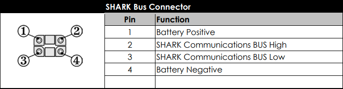
Pins 2 and 3 show communications bus HIGH and LOW. At first glance you would assume this is a CAN bus or similar. The documentation states that this is a proprietary bus and Dynamic Controls states it is not possible to interface with. Clearly we know this is partially inaccurate. Connecting an oscilloscope to the HIGH line of the bus yielded something interesting upon turning on the joystick.
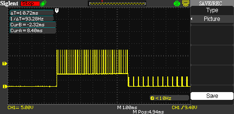
We can see in the photo above that the waveform looks a bit odd. Not quite like most serial communications. Closer examination shows the initial pulse is the HIGH line pulled high to 5V, while at the same time being pulled to system battery voltage for approximately 300ms. In this case the battery voltage is ~24V – 26V as we have a 24V wheelchair. I later learned that this initial 300ms pulse is used to latch the power controller in the on-state. This pulse can be 300ms +/- 20ms.
Continuing, if we ignore the 300ms 24V pulse, and look closer at the next part of the waveform, we can see the following:
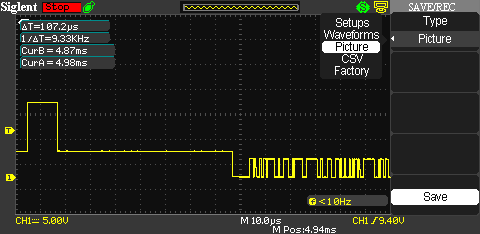
We’re looking at the section directly past the center of this waveform. This looks more like a serial communication line now… and after measuring the smallest single bit of this waveform, we measure the time bias to come up with a baud rate of 38400 with 1 start bit and two stop bits. Looking at the LOW shark bus line reveals the same waveform, but inverted, with an exception to the initial startup pulse. To summarize, we have figure out that this is not a CAN bus, but an RS485 serial bus running at a baud rate of 38400, again with 1 start bit and two stop bits.
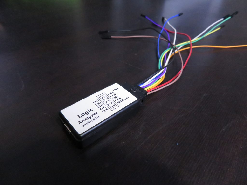
Since we now know the communication type, we should be able to monitor the bus. In the next part I got out my logic analyzer I purchased on eBay. A 24MHz 8 channel USB logic analyzer for $11 USD.
Paired with the latest version of the Saleae Logic software, this is an excellent tool to use to figure out what’s going on within our Shark Bus. Using the settings below, I connected the analyzer and at a 12MHz speed, over a 20 second period, I was able to read the data with only a single framing error from the initial 300ms pulse.
Saleae Analyzer Setup Settings:
Asynchronous Serial
Bit Rate: 38400
8 Bits per Transfer
2 Stop Bits
No Parity Bit
Least Significant Bit Sent First
Inverted

If you recall, I was still using information I found from wheelchairdriver.com to assist me throughout this process, and this is where it’s different for each application. If your power controller model is not exactly the same as the one I’ve been reverse engineering, chances are you will need to make adjustments along the way. Otherwise, if you have exactly the same hardware as me, you’re good to go.
After examining the data, we can see that each group is separated by some noticeable dead points, and right before each of these dead spots, we read “15”. This must be a packet terminator. In my case, most of the packets seem to begin with “`” or “!”, with an exception to the first and second. The first packet seems to begin with “t” and only occurs once in the entire dump. Same as the second packet that begins with “5”. We can assume these packets are required to begin communicating with the power base, but why two? Surely there’s a pattern here.


If we look at the above packet in our capture, starting with “`”, we can see shortly after, it is followed by another packet starting with “!”, as is every instance of this packet. Based on the 2ms timing of this packet after the initial “`” packet, with the longer 12ms period after the “!” packet, we can assume this is some sort of response from the power controller.

If we assume this is a response or acknowledgement packet, then perhaps the first packet also has a response… Again we look at the second packet starting with “5” shown below. It doesn’t really seem to have much information in it. “128” and “250”. What if this is also a response to the first packet?
This is where I found a very important piece of information presented from wheelchairdriver.com. A document describing precisely how the Shark Bus protocol works. Seriously? After all this time, NOW I’m presented with it? Not sure how it was acquired, but I was unable to find this document anywhere else on the internet. Here it is for your reference:
Continuing on, if we look at the document, it states something we’ve already learned.
The wakeup signal on the SBH wire shall be asserted for 300ms +/- 20ms. During this time, the SPM is required to power up, stabilise its operation and latch its power on so that it does not power down again when the wakeup signal is removed. Note that communication on the Shark Bus is not possible when wakeup signal is present. The wakeup signal transmitter shall be designed so that it can source 40mA at greater than 12V, under all normal battery conditions (see Hardware Specification), for the full 300ms.
That’s very accurate, though until this point we didn’t know it was only 12V that was required to wake up the power controller (SPM – Shark Power Module).
Lets look at section 5 referring to packet structures. It states that each packet ends with a Transmit Finished byte with a value of 0x0F or “15” in decimal. Information has been validated. Continuing; there is a section labeled “Immediately after power-up with SACU in system” that describes the first packet as SR power-up information. SR In this document refers to the remote. This packet is also terminated with 0x0F or “15”. The next packet is described as the SPM or power controller’s power-up information packet, which is a result of the remote sending its power-up packet, and lastly but not present in our system is the SACU (Attendant Control Unit) power-up information packet. We’ll ignore this, as one is not present.
We’ve now learned what the following packets are for:
That leaves two more packets from my dump, which I’ve been referring to as the “`” and “!” packets. As the document now shows us in the “Normal Operation, no HHP traffic” section; these packets in sequential order are the SR general information and SPM general information packets. This is a major breakthrough. Page 5 and so on describes the contents of each packet and as a result we are now ready to attempt to communicate with our SPM.
The Hardware
To be continued…
You might find some of my earlier work helpful in your efforts… https://github.com/jimconner/sharkbus – I have the full details of the sharkbus spec which I can send to you.
Excellent work! I’ve been trying to figure out a good way to control a Shark Bus wheelchair VIA RC (S-Bus).
No good options exist, though I’ve read Jim’s work on wheelchairdriver.com
On other projects, I’ve just used an ESC to drive the wheel motors directly, but on my most recent donor chair I have linear actuators with very accurate position sensors. I’d like to utilize them VIA RC control for a project.
I’d love to see (and buy) any device that could translate PWM or S-Bus signals to the Shark Bus protocol!
Ultimately I want to use Ardurover to run the system, which is capable of controlling VIA PWM or S-Bus…
Thank you very awesome
Hi, thanks for your work. I want to hack my old invacare wheelchair and would like you to send me the full specs of the sharkbus.
Greetings
Hello! There are updates?
Is there any further progress? this looks very interesting